MEP Coordination Best Practices
Learn how BIM clash detection, RFI management, and contractor-led field coordination can help project teams reduce conflicts and rework.
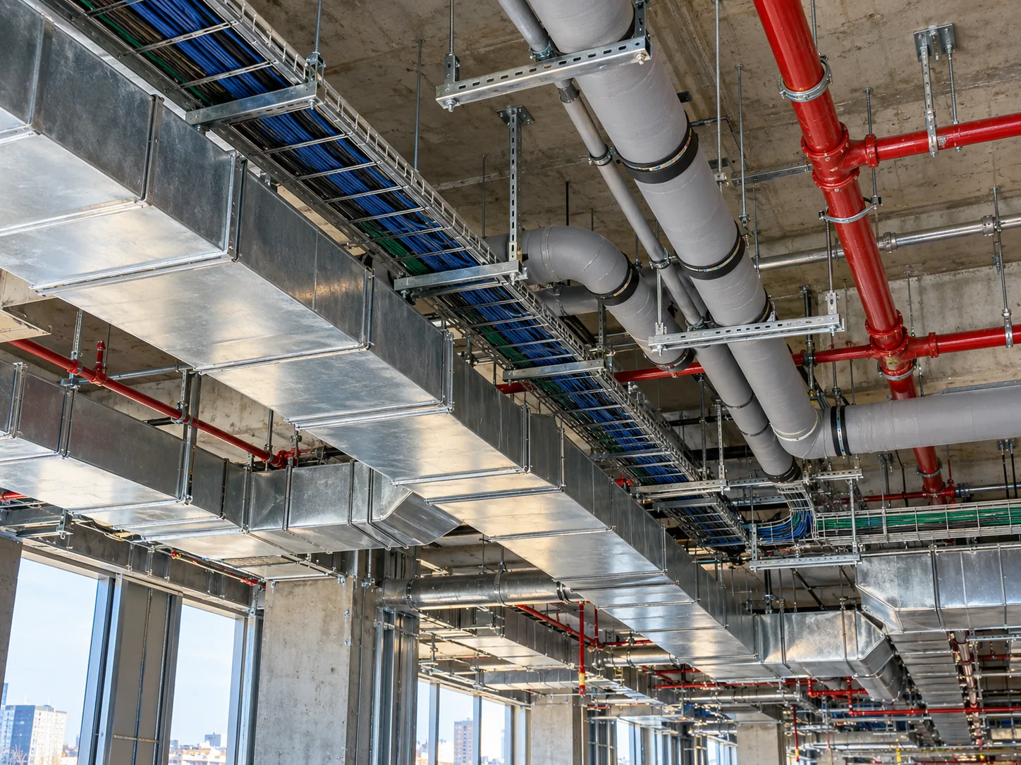
- Design-phase coordination is the engineer's job; construction-phase coordination is contractor-led.
- The cost to resolve a clash on paper is usually lower than what the same conflict costs to resolve on-site.
- The skill is prioritizing the clashes that matter and driving those to closure.
MEP coordination makes mechanical, electrical, plumbing, fire-protection, structural, and architectural systems fit together before installation. Done well, it helps a set clear review and keeps the field moving; done poorly, it creates clashes, delays, and RFIs.
MEP coordination helps mechanical, electrical, plumbing, fire-protection, structural, and architectural systems fit together and reduces conflicts. It runs in two phases: design-phase coordination (the engineer coordinates the disciplines in the design model and set) and construction-phase coordination (the contractor's BIM/VDC team runs clash detection on fabrication-level models). The goal is the same — resolve as many conflicts as possible on a screen rather than in the field.
Why MEP Coordination Matters
Mechanical, electrical, and plumbing systems occupy the same spaces — walls, ceilings, chases, electrical rooms. Without coordination, they compete for real estate:
- Ductwork and conduit both want the same ceiling cavity.
- A plumbing riser and structural column occupy the same vertical zone.
- Equipment access points conflict with architectural elements.
When uncoordinated conflicts are discovered on-site, they can require emergency redesigns, field cuts, rerouting, and schedule delays. A single unresolved conflict can be substantially more expensive to fix in the field than it would have been to resolve in the model, depending on severity and timing.
Design Coordination vs. Construction Coordination
"MEP coordination" actually names two connected but distinct efforts, and confusing them is where projects go wrong:
- Design-phase coordination is the engineer's job. Working in the design model, the MEP team coordinates ducts, pipe, conduit, and equipment against each other and against structure and architecture, and delivers a set that's already been checked for the obvious conflicts. It's design intent, coordinated — not fabrication-level.
- Construction-phase coordination is contractor-led. The GC or a VDC team federates the trades' detailed models, runs formal clash detection, and produces the coordination and shop drawings the trades actually build from. The MEP engineer participates in and reviews this — answering RFIs, confirming the resolutions still meet design intent — but the contractor and its subcontractors own the means-and-methods coordination and the fabrication models.
The handoff between them is where discipline pays off: a well-coordinated design set gives the construction team a clean starting point, and a construction team that flags design conflicts early keeps the engineer's RFIs small. Naming who owns each phase up front is itself a best practice — it's a quick way to avoid the "I thought you were coordinating that" gap. Many projects put this in writing as a BIM Execution Plan (BEP) — a short agreement, set at kickoff, on who coordinates what, at what LOD, and with which tools.
The Coordination Workflow
Best-practice coordination follows this timeline:
- Schematic Design: MEP engineer establishes system concept and approx. equipment locations.
- Design Development: Coordination drawings are created showing all three disciplines overlaid. A coordination meeting is held to review conflicts on paper and assign resolutions. Conflicts are marked on the drawing (coordination items).
- Construction Documents: Resolve design-level coordination items in the appropriate plans, sections, schedules, and details before CD release; document any remaining open items with a named responsible party and an agreed resolution milestone. The drawing set should be checked for design-level conflicts before it goes to the contractor, and any open items assigned to a named party.
- Bid Phase: Contractors review CDs and submit written clarification questions through the project's bidding procedure. Formal interpretations and changes to the bidding documents are issued by addendum where required by that procedure.
- Construction: Field coordination often occurs daily as trades encounter situations not fully anticipated in design. A project coordinator or MEP superintendent manages on-site decisions and documents changes.
BIM & Clash Detection
Building Information Modeling (BIM) is a digital representation of a building's physical and functional characteristics, typically a 3D model of its architecture, structure, and the systems in scope. BIM clash detection tools automatically find overlaps:
- Architectural BIM: Walls, floors, doors, windows, rooms.
- Structural BIM: Beams, columns, slabs, bracing.
- MEP BIM (combined or separate M, E, P): Equipment, piping, ductwork, conduit, distribution systems.
When models are merged in BIM software (e.g., Revit, Navisworks), clash detection runs automated checks: "Where does mechanical ductwork intersect electrical conduit?" Results are exported as a "clash report" listing each clash detected by the configured tests, with its location and the items involved; the team then reviews and prioritizes them.
Clash Detection Workflow
- Model preparation: Each discipline models its systems to the level of development agreed for each element and its intended coordination use, often recorded in the BIM Execution Plan.
- Coordination review meeting: All models are merged, clash detection is run, and the team reviews results together.
- Clash assignment: Each clash is assigned to the discipline responsible for resolution (e.g., "Mechanical, relocate ductwork 12 inches west").
- Model revision: Each responsible team updates its models to resolve assigned clashes.
- Re-detection: Clash detection is re-run to confirm clashes are resolved.
- Documentation: Resolved clashes are documented in coordination details before CD release.
Levels of Development (LOD): How Detailed Is the Model?
BIM coordination only works if everyone agrees how developed each element is — that's what Level of Development (LOD) defines. It's the shared vocabulary that tells a coordinator whether a duct in the model is a rough placeholder or fabrication-ready:
| LOD | Roughly means | Typical phase |
|---|---|---|
| LOD 100 | Conceptual (mass/area) | Early design |
| LOD 200 | Approximate geometry | Schematic / DD |
| LOD 300 | Accurate design geometry | Design set (engineer's coordination) |
| LOD 350 | Design + interfaces to other trades | Design→construction handoff |
| LOD 400 | Fabrication/installation detail | Construction coordination (by others) |
| LOD 500 | As-constructed / existing conditions | Closeout |
The practical point maps straight onto the phase split: the design team typically coordinates around LOD 300–350, while the LOD 400 fabrication-level clash detection lives with the construction team (by others). Arguing about a clash without agreeing on LOD is arguing about two different models. The BIMForum LOD Specification, built on the AIA's original LOD framework, is the industry-standard reference for the full element-by-element definitions.
The Coordination Toolchain
Coordination runs on a fairly standard set of tools, and knowing what each does clarifies the workflow:
- Revit — where many disciplines model today (some teams still work in AutoCAD MEP, but the coordination principles are the same). Coordination within the design happens here through linked models, shared coordinates, and Copy/Monitor (which flags a change to a monitored element like a grid, or a floor opening such as a major shaft, for coordination review), with worksharing letting a team work the same model.
- Navisworks (and also Revizto / Solibri) — where models from every trade are federated into one and clash detection is run: clash tests between systems, grouped and prioritized results, saved viewpoints, and reports that drive resolution. This is the heart of construction-phase coordination (by others).
- Autodesk Construction Cloud / BIM 360 (ACC) — the common-data environment where models, clashes, and RFIs are shared across the team. Models typically exchange through native formats or the open IFC standard, and, where the owner requires it, completed systems hand off asset data through COBie for the owner's facilities team.
The engineer lives mostly in Revit (design coordination) and reviews the federated model in Navisworks; the construction team and its subcontractors live in that federated model for fabrication-level clash resolution. Same toolchain, different phase, different owner.
The Coordination Matrix and Clash Prioritization
Two artifacts keep coordination from becoming chaos:
A coordination matrix assigns priority in congested space — which system yields to which when they compete for the same ceiling. This matters most in tight-tolerance spaces like healthcare corridors or data-center white space, where systems compete for the same few inches. A common ordering (project-specific, but broadly):
| Priority | System | Why |
|---|---|---|
| 1 | Structure | Fixed; everything routes around it |
| 2 | Gravity plumbing / storm | Slope-constrained, can't move freely |
| 3 | Large ductwork | Big, hard to reroute |
| 4 | Fire protection (by others) | Coordinated input, code-driven layout |
| 5 | Pressurized pipe | More reroutable |
| 6 | Conduit / cable tray | Most flexible |
Clash prioritization sorts detected clashes by severity — hard clashes (a duct through a beam) usually rank high; soft clashes (clearance/access violations) often rank medium, but severity depends on consequence, not clash type alone: a clearance violation that blocks required electrical working space or equipment access ranks high; many "clashes" are model noise to filter out. Clash prioritization separates consequential conflicts from model noise and drives the relevant issues to closure.
Trade Sequencing and Prefabrication
The end-to-end coordination workflow, spanning both phases:
Architecture and structure set the envelope → each MEP discipline models to LOD 300–350 → models are federated → clash detection → coordination meetings assign and track resolutions → design conflicts route back to the engineer as RFIs → resolved model → fabrication-level (LOD 400) coordination (by others) → shop/coordination drawings → build.
This tracks the same phases we cover in detail in our guide to MEP design phases (SD, DD, and CD) — coordination is what happens inside and between those phases. A constructability review — confirming the coordinated model can actually be built the way it's drawn, with real access for tools, people, and material handling — is typically part of this handoff.
The GC sets physical trade sequencing with the trades, considering access, supports, inspections, prefabrication, and closure dates. The spatial-priority matrix informs coordination but does not prescribe installation order.
Why Coordination Enables Prefabrication
Do all of this well and you unlock prefabrication: because the model is well coordinated, contractors can fabricate multi-trade racks and assemblies off-site and install them with less rework — a potential schedule and cost benefit of good coordination. This can pay off especially on multifamily and residential projects, where repetitive unit layouts mean a single coordinated rack or riser detail gets built dozens of times over. (Prefabrication is a construction-team capability (by others) — the coordinated design set is what makes it possible.)
RFI Management Best Practices
An RFI (Request for Information) is a formal question submitted by a contractor to the design team requesting clarification or resolution of an ambiguity.
What Triggers a Good RFI
- A conflict or interference shown on drawings without a clear resolution detail.
- Ambiguous specifications or conflicting notes on different sheets.
- A field condition that differs from what the drawings show.
- Equipment that doesn't fit in the space as drawn.
RFI Best Practices
1. Submit early: Don't wait until a trade is on-site to ask. Raise bid questions before the bidding deadline and construction-phase RFIs before affected work depends on the answer.
2. Be specific: Include drawing sheet numbers, detail references, dimensions, photos, and a clear description of the problem. "This doesn't work" is not an RFI. "Sheet M-3.2 shows 8-inch ductwork routing through the ceiling at grid C4, but the available depth is only 6 inches due to the structural beam above. How should this duct be routed?" is a good RFI.
3. Propose alternatives: If you see multiple solutions, ask which the engineer prefers rather than just asking for clarification. This speeds response.
4. Track RFIs centrally: Use a shared log or project management tool to track all RFIs, response dates, and resolutions. This prevents duplicates and ensures accountability.
5. Don't ignore RFI responses: Some contractors receive an RFI response and never implement it. Document the response and implement it in accordance with the contract. An RFI response does not by itself authorize a contract change. If it affects scope, cost, or time, follow the contract's notice, authorization, and change procedures; authorized work may proceed before its price or time adjustment is agreed.
A Simple Issue Log
Tracking doesn't need special software. Five columns cover it. The row below is an illustration built from the example RFI above, not project data:
| Issue | Identified by / date | Owner | Decision | Closed |
|---|---|---|---|---|
| Illustrative: Sheet M-3.2, 8-inch duct at grid C4; only 6 inches of depth below the beam | Mechanical contractor, [date] | MEP engineer | [Response and revised detail reference] | [Date closed] |
On-Site Coordination
Even the best-coordinated design encounters field situations — unexpected obstructions, code inspector requests, change orders. On-site coordination helps keep these from becoming schedule killers.
Field Coordination Best Practices
- Appoint a coordinator: A dedicated person (often the MEP superintendent or general contractor's coordinator) manages daily coordination decisions, photos, and communications between trades.
- Daily coordination meetings: On-site trades (plumbing, mechanical, electrical) meet daily for 10–15 minutes to align on the day's work, flag conflicts, and resolve access issues.
- Document everything: Photos of every conflict, decision, and workaround are stored in a project folder. This protects all parties and helps prevent "I thought we agreed" disputes.
- Address conflicts immediately: If two trades want the same space, don't let them both start work hoping it resolves itself. Pause one and request urgent direction from the MEP engineer or project manager.
- Verify vs. assumptions: If the field condition differs from drawings (e.g., a beam is in a different location), verify the actual dimension before building around it. A quick measurement can save hours of rework. On renovation and retrofit work, the contractor's VDC team may laser-scan existing conditions into a point cloud before coordinating new systems around them (by others) — a far more reliable baseline than as-built drawings alone.
Common MEP Conflicts (And How to Resolve Them)
1. Ductwork + Electrical conduit in the same ceiling cavity: Solution: relocate one — conduit to a higher tray or a dedicated riser is usually the cheaper move — or gain depth by lowering the ceiling. If the duct must change, resize it and re-run the pressure and acoustic calculations; do not shrink it on the drawing to make it fit.
2. Plumbing riser + structural column: Solution: offset the riser horizontally into the adjacent wall, or route around the column with offset fittings. If neither works, coordinate a structural opening or relocate the fixture group — do not reduce pipe size to clear the obstruction, and re-check stack-offset sizing and venting under the adopted plumbing code.
3. Equipment access blocked by another system: Solution: provide the code-required working clearance in the design. Relocate the blocking system, add removable access panels where the required clearance is still provided, or move the equipment. Do not rely on disconnecting a system for maintenance access — clearance is a design requirement, not an operating procedure.
4. Fire-rated wall penetration unclarified: Solution: the drawings and specifications should clearly state the fire rating required (2-hour, 1-hour, etc.) and the tested fire-stop system (for example, a UL system number) for each penetrant, including the sleeve where that system uses one. Penetrations of fire-rated assemblies must comply with the adopted building code. Through-penetrations generally require an approved fire-stop system installed as tested to ASTM E814 or UL 1479, unless a specifically permitted alternative applies. Membrane penetrations have separate provisions and exceptions. Ducts and air-transfer openings protected with dampers follow IBC Section 717; undampered penetrations also require Section 714 protection where applicable.
5. Undersized service entry or distribution: Solution: identified early (via coordination), it can mean a revised load calculation and a larger service or distribution, coordinated with the utility. Identified late, it can mean replacing ordered gear, reworking the utility application, and delay.
Related: MEP Design Phases (SD/DD/CD) · How to Read MEP Drawings · What Are MEP Drawings?
Common Questions
MEP coordination is the process of helping mechanical, electrical, and plumbing systems fit together with fewer conflicts. It matters because unresolved conflicts can cause delays, change orders, rework, and safety issues. A coordination meeting during design usually costs less than resolving the same conflict after installation begins, in labor, materials, and schedule impact.
BIM (Building Information Modeling) software allows 3D models from each discipline (architectural, structural, MEP) to be combined. Clash detection tools then automatically flag overlaps where, for example, ductwork intersects an electrical panel. Each detected clash is documented, and the responsible design or trade team resolves it by adjusting routing or equipment location, with proposed changes affecting design intent or performance referred to the engineer of record for review. This helps catch problems on paper, before they reach the site.
An effective RFI includes: a clear description of the conflict or question, reference to drawing sheet numbers and detail numbers, a photo or sketch showing the problem, dimensions or coordinates if location-specific, the impact if unresolved (delay, cost, safety), and a specific request for clarification or solution. The more detail you provide, the faster the engineer can respond with a solution.
Coordinating building systems inside a 3D BIM environment by federating each discipline's model and running clash detection, rather than overlaying 2D drawings.
Automatically finding where modeled systems physically conflict (a duct through a beam) or violate clearances, so they're resolved on screen instead of in the field.
Revit for modeling, Navisworks (or Revizto/Solibri) for federating models and running clash detection, and a common-data environment like Autodesk Construction Cloud / BIM 360 for sharing.
It's shared by phase: the MEP engineer leads design-phase coordination; the GC or VDC team leads construction-phase (fabrication-level) coordination, with the engineer reviewing and resolving design conflicts.
Level of Development — a standard that defines how detailed and reliable a model element is, from LOD 100 (conceptual) to LOD 400 (fabrication); LOD 500 records as-constructed or existing conditions and is not a higher level than LOD 400.
Composite drawings showing all trades together, used to prove systems fit and to guide installation; fabrication-level coordination drawings are typically produced in construction-phase coordination.
A Request for Information — a formal question raised (often during coordination) when the documents need clarification or a conflict needs a design decision.
In design, as early as the systems are modeled — resolving conflicts is usually cheapest early; construction-phase coordination follows once trades develop fabrication models.
A recurring working session where the team reviews the federated model and clash reports, assigns resolutions, tracks them, and confirms closure.

Senior electrical designer with 6+ years in U.S. MEP design, contributor to 900+ projects, and an experienced third-party peer and plan reviewer.
Connect on LinkedIn →