Commercial Kitchen Exhaust: Hoods, Grease Ducts & Make-Up Air
How Type I hoods, grease ducts, make-up air and fire-suppression interlocks fit together under the IMC and NFPA 96, and what a plan reviewer checks before the set is approved.
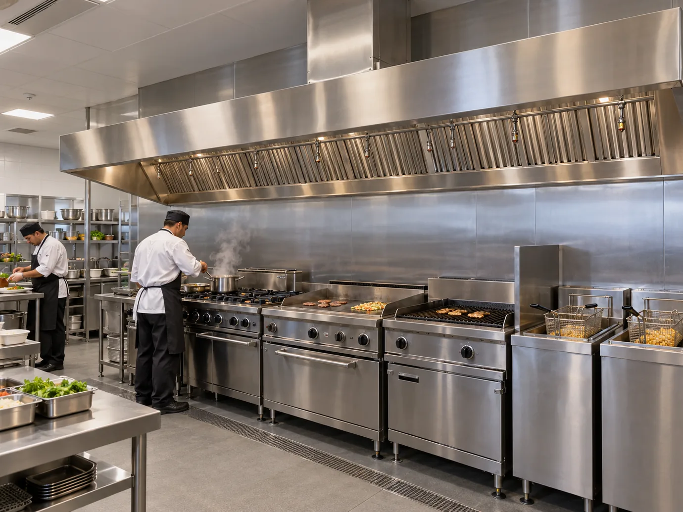
- Grease- or smoke-producing appliances need a Type I hood, designed as one system with the duct, fan, make-up air and suppression interlocks.
- Grease ducts are welded steel, sloped to the hood, sized for at least 500 fpm, cleanable, and cleared or enclosed as required.
- Common review comments are mismatches: exhaust vs. hood, make-up air vs. exhaust, duct route vs. clearances.
Kitchen exhaust is a fire-safety system first and an HVAC system second. The mechanical code (IMC Chapter 5 in many states; the UMC in states such as California, which carries NFPA 96 text) sets the hood type, exhaust rate, grease duct construction and termination, and NFPA 96 applies wherever the fire code adopts it. The energy code adds limits once total hood exhaust passes 5,000 cfm. A set that holds up in review shows the appliance schedule, hood listing and exhaust rate, the duct route with slope, access and clearances, the make-up air balance and the interlock sequence, and they all agree.
A commercial kitchen hood is one of the few HVAC systems that the building plan reviewer, the fire marshal and the health inspector all look at. It captures heat, smoke and grease-laden vapor at the cooking line, carries the grease through a duct that has to stay cleanable and fire-safe, and only works if the make-up air and the fire-suppression interlocks work with it.
Section numbers below are from the 2021 International Mechanical Code (IMC). Confirm the edition and the local amendments your jurisdiction enforces: states on the Uniform Mechanical Code (California's CMC, for example) carry NFPA 96 text directly, some jurisdictions replace the IMC kitchen sections with NFPA 96, and local amendments to hood, make-up air and duct rules are common. The physics is the same everywhere; the numbers and section references move.
Type I or Type II: Which Hood Is Required
The IMC requires a Type I hood wherever cooking appliances produce grease or smoke (IMC 507.2): fryers, griddles, charbroilers, ranges, woks and similar equipment. A Type II hood handles heat, steam and moisture from appliances that produce no grease or smoke, such as dishwashers. The difference matters: only a Type I hood connects to a grease duct, and the appliances that require it must be protected by an automatic fire-extinguishing system (IMC 509.1).
The code allows narrow exceptions. An electric appliance whose effluent tests at 5 mg/m³ of grease or less at 500 cfm under UL 710B, documented by an approved testing agency, does not need a Type I hood, and listed recirculating systems (UL 710B) and listed hoods (UL 710) are installed to their listings. Whether an exception applies is the AHJ's call, so it belongs on the drawings, not in an assumption.
All of this starts from the appliance schedule. The hood type, length and exhaust rate follow from what sits under the hood, so the kitchen consultant's equipment list, with each appliance's duty, is the first document to lock down.
Exhaust Rate: Listed vs. Unlisted Hoods
Most commercial kitchens use listed hoods (UL 710). The hood's label states the minimum exhaust rate, in cfm per linear foot, needed for capture and containment over the appliances it was listed for, and the design follows that listing.
Unlisted hoods are sized from the IMC's minimum rates (507.5) by appliance duty (light, medium, heavy, extra-heavy) and hood style. For example, a wall-mounted canopy needs 400 cfm per linear foot over heavy-duty appliances and 550 over extra-heavy (solid-fuel) appliances; a single-island canopy, open on all sides, needs 600 and 700. An unlisted canopy hood also has to overhang the appliances by at least 6 inches on all open sides, with its front lip no more than 4 feet above the cooking surface (IMC 507.4.1), and a Type I hood needs 18 inches of clearance to combustible material.
The rate drives everything downstream: the duct size (to hold velocity), the fan, the make-up air quantity and, above 5,000 cfm, the energy-code compliance path. Getting it right once, from the appliance schedule, avoids re-sizing all of them later.
Grease Duct Construction
A grease duct is not ordinary ductwork. Under the IMC (506.3) it is:
- Steel at least 0.0575 in. thick (No. 16 gage) or stainless steel at least 0.0450 in. (No. 18 gage). NFPA 96, and the UMC that extracts it, specifies 0.060 in. carbon steel (No. 16 MSG) or 0.048 in. stainless (No. 18 MSG). Listed factory-built grease duct (UL 1978) follows its listing.
- Joined with continuous, liquid-tight welds or brazes on the external surface, so grease cannot leak out and burn in a concealed space.
- Sloped back toward the hood or an approved grease reservoir at not less than ¼ in. per foot, and at not less than 1 in. per foot where a horizontal run is longer than 75 feet (IMC 506.3.7).
- Sized for at least 500 fpm at the design exhaust rate (IMC 506.3.4; NFPA 96 sets the same minimum, and the UMC also caps velocity at 2,500 fpm), so grease keeps moving toward the fan; velocity alone does not prevent deposits, which is why the slope and cleanouts still matter.
- Leak-tested before it is concealed. The 2021 IMC uses a light test with a lamp of at least 100 watts; the 2024 edition moves to a lamp of at least 1,600 lumens and adds a water-test option.
Routing, Clearances & Enclosure
The route is where most grease duct problems start, and it has to be settled while the architecture is still flexible.
Access for cleaning. The IMC requires cleanouts on horizontal runs no more than 20 feet apart and within 10 feet of changes of direction greater than 45 degrees. NFPA 96 takes a different approach (openings at changes of direction, and on horizontal runs either a personnel-entry opening or cleaning openings at 12-foot intervals), so the governing document has to be identified before the openings are laid out. Every access point has to be reachable from the space it is in.
Clearances. Where no enclosure is required, the IMC requires 18 inches to combustible construction and 3 inches to noncombustible construction (IMC 506.3.6). NFPA 96 requires 18 inches to combustible, 3 inches to limited-combustible and 0 inches to noncombustible material. Clearances can be reduced only by the methods the code allows, such as a listed factory-built duct or a listed field-applied enclosure tested to ASTM E2336.
Enclosure. Where a grease duct penetrates a ceiling, wall, floor or concealed space, the IMC requires it to be enclosed from that point to the outlet (IMC 506.3.11): in a shaft built to the IBC's shaft rules, in a listed field-applied enclosure (ASTM E2336), or in a listed factory-built enclosure (UL 2221). The exception that matters most often: no enclosure is required where the duct penetrates only a non-fire-resistance-rated roof/ceiling assembly. That shaft or wrap takes space, and it has to be on the architectural plans as well as the mechanical ones.
Exhaust Fan & Rooftop Termination
The exhaust fan has to suit grease service: under IMC 506.5.1 its housing is built to grease-duct construction or the fan is listed to UL 762, and its motor sits outside the airstream (506.5.1.1). Under NFPA 96, an upblast fan is hinged, with flexible weatherproof cable and a service hold-open retainer so the duct and fan can be cleaned, and drains to a visible grease receptacle of not more than 1 gallon.
The discharge location is checked against fixed distances. Under the IMC, a rooftop outlet discharges at least 40 inches above the roof (506.3.13.1) and is kept 10 feet horizontally from parts of the same or adjacent buildings and from property lines, 10 feet above grade, and at least 10 feet horizontally from an air intake or 3 feet above it (506.3.13.3). NFPA 96 sets similar distances and also requires the duct to rise at least 18 inches from the roof surface at a hinged fan. Outdoor-air intakes on nearby rooftop units are easy to miss, so these distances are worth checking before the roof layout is fixed.
The fan also has to run when the cooking line does. The 2021 IMC (507.1.1) requires a Type I hood system to start the exhaust fan automatically whenever cooking operations occur, and NFPA 96 requires a means to activate the fan when any heat-producing appliance under the hood is on.
Make-Up Air
Every cubic foot exhausted has to come back in. The IMC requires make-up air approximately equal to the exhaust, supplied whenever the exhaust runs, with mechanical make-up air interlocked to the exhaust fan (IMC 508.1). Its temperature may differ from the kitchen's by no more than 10°F unless the added heating and cooling load is within the HVAC system's capacity (IMC 508.1.1), which in practice means tempered make-up air in most climates.
Where the make-up air enters matters as much as how much. Air discharged into the hood cavity (a compensating hood) is limited to 10 percent of the hood exhaust under ASHRAE 90.1, and the UMC sets the same limit for compensating hoods. Supply diffusers should not blow across the hood face, and the kitchen is normally held slightly negative to the dining room so cooking odors stay in the kitchen. Too little make-up air shows up as doors that are hard to open, pilot lights that misbehave and hoods that spill smoke.
Suppression Interlocks & Who Designs What
A Type I hood over grease-producing appliances needs an automatic fire-extinguishing system, typically a listed wet-chemical system tested to UL 300. On activation, NFPA 96 requires all sources of fuel and electric power that produce heat in the protected equipment to shut off automatically, including gas appliances under the same hood that do not themselves need protection; solid-fuel cooking and steam supplied from an external source are the exceptions. Shutoff devices must be manually reset before fuel or power is restored, and an electric gas valve gets a manually reset relay. The exhaust fan keeps running unless a listed component or the extinguishing system requires it to stop, and make-up air supplied internally to the hood shuts off.
The boundary between trades has to be clear on the drawings:
- By the fire-suppression contractor: the listed wet-chemical system itself, its nozzles, piping, detection and manual pull station.
- By the MEP design: the location of the gas shut-off valve on the fuel gas piping (the valve itself is typically furnished with the suppression system), the electrical shut-down of protected cooking equipment (shunt trip or contactor), the exhaust and make-up air fan sequences, and the fire-alarm interface where the building has a fire alarm system.
Showing that sequence as a short interlock table (event, then fan, make-up air, gas and power response) answers many of the reviewer's questions before they are asked.
The Energy Code Above 5,000 cfm
Once a facility's total kitchen hood exhaust exceeds 5,000 cfm, ASHRAE 90.1-2019 (6.5.7.2) and the 2021 IECC (C403.7.5) add limits, and the 2021 IECC also requires each hood to be listed to UL 710. First, each hood is limited to a maximum net exhaust rate per linear foot, set by hood type and the highest appliance duty under it (90.1 Table 6.5.7.2.2; for a wall-mounted canopy over heavy-duty equipment, 280 cfm per foot), unless at least 75 percent of the replacement air is transfer air that would otherwise be exhausted. Second, the design must use one of three measures:
- at least 50 percent of the replacement air is transfer air that would otherwise be exhausted;
- demand-controlled kitchen ventilation on at least 75 percent of the exhaust, able to reduce exhaust and replacement airflow by at least 50 percent; or
- listed energy recovery serving at least 50 percent of the total exhaust airflow, with at least 40 percent sensible heat recovery effectiveness under the IECC (a sensible energy recovery ratio of at least 40 percent under ASHRAE 90.1).
Later editions revise this section (the 2024 IECC, for example), so the measure has to match the edition your jurisdiction has adopted. Note that the energy-code maximum is a ceiling and the hood listing is a floor: the selected hood has to operate at a rate between the two. An unlisted hood sized at the IMC minimums (400 cfm per foot for a wall canopy over heavy-duty equipment) already exceeds the 90.1 maximum of 280, which is one reason facilities above 5,000 cfm use listed hoods.
What a Reviewer Checks
From the reviewer's side, a kitchen exhaust package is checked as a chain, and each link has to agree with the next:
- Appliance schedule with each appliance's duty, matched to the hood length and type.
- Hood exhaust rate from the listing (or IMC 507.5 for an unlisted hood), and the energy-code maximum where it applies.
- Grease duct: material and thickness, welded joints, slope, velocity, cleanouts, clearances or enclosure rating, and the leak test noted for inspection.
- Roof plan showing the fan, the 40-inch discharge height and the distances to intakes, property lines and adjacent buildings.
- Make-up air scheduled to balance the exhaust, tempered as required, and interlocked.
- Interlock sequence for suppression activation, with the suppression system itself noted as by the suppression contractor.
- Energy compliance: the hood-cavity and conditioned-supply-air limits on every kitchen exhaust system, plus the added requirements where total hood exhaust exceeds 5,000 cfm.
The kitchen also drives the plumbing (grease interceptor, indirect waste, hot water) and the electrical (equipment connections, interlocks); MEP for Restaurants covers how those systems fit together, and Duct Sizing covers the static-pressure side of the fan selection.
Further reading: MEP for Restaurants · Duct Sizing (Equal Friction / Static Regain) · 7 Common Plan-Check Comments
Your engineer of record stays in responsible charge, directing the design decisions, reviewing and sealing. CoreX prepares the production drawings and calculations for the hood exhaust, make-up air, grease duct routing, fuel gas and electrical interlocks, coordinated across the MEP set; the suppression system itself is by the suppression contractor under that direction. Code references in this article are general guidance, so confirm the requirements for your project with your AHJ and engineer of record. See our HVAC services and restaurant work, or schedule a scope call.
Common Questions
Under the IMC (507.2), wherever cooking appliances produce grease or smoke, such as fryers, griddles, charbroilers and ranges. Appliances that produce only heat or moisture, such as dishwashers, use a Type II hood unless their heat and moisture loads are carried in the HVAC design or a separate removal system. An electric appliance whose effluent tests at 5 mg/m³ of grease or less at 500 cfm under UL 710B, documented by an approved testing agency, is excepted, subject to the AHJ.
Under the IMC, steel at least 0.0575 in. (No. 16 gage) or stainless steel at least 0.0450 in. (No. 18 gage), with continuous liquid-tight external welds. NFPA 96 and the UMC specify 0.060 in. carbon steel or 0.048 in. stainless. Listed factory-built grease duct (UL 1978) follows its listing.
At least ¼ in. per foot toward the hood or an approved grease reservoir, and at least 1 in. per foot where a horizontal run is longer than 75 feet (IMC 506.3.7).
Approximately as much as the hood exhausts, supplied whenever the exhaust runs and interlocked with the exhaust fan (IMC 508.1). Unless the HVAC system can carry the extra load, make-up air has to be within 10°F of the space temperature (IMC 508.1.1).
The listed wet-chemical system is designed and installed by the fire-suppression contractor. The MEP design covers what connects to it: the gas shut-off location on the fuel gas piping, the electrical shut-down of protected cooking equipment, the exhaust and make-up air fan sequences, and the fire-alarm interface.
Under the IMC, at least 40 inches above the roof surface (506.3.13.1), and at least 10 feet horizontally from parts of the same or adjacent buildings and from property lines, 10 feet above grade, and 10 feet horizontally from (or 3 feet above) any air intake (506.3.13.3). NFPA 96 sets similar distances.

Senior electrical designer with 6+ years in U.S. MEP design, contributor to 900+ projects, and an experienced third-party peer and plan reviewer.
Connect on LinkedIn →