Duct Sizing: Equal Friction, Static Regain, and Static Pressure
A good load calculation either gets delivered or quietly wasted at the ductwork. Here's how the main sizing methods differ, and why static pressure keeps everyone honest.
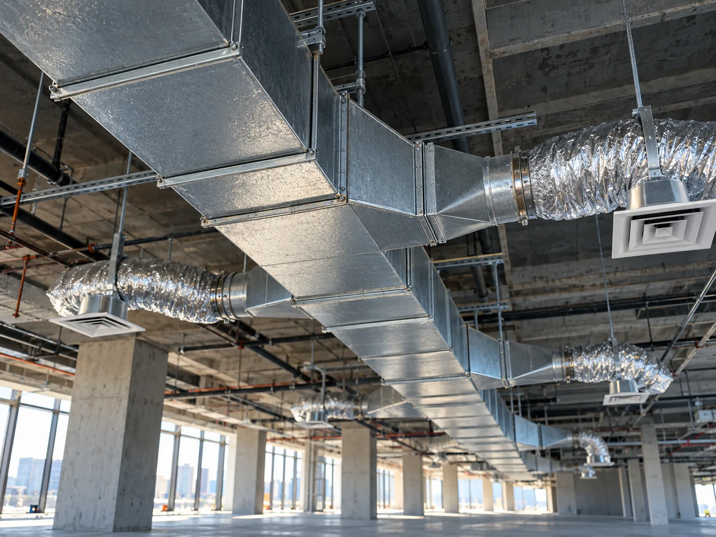
- Equal friction is the default for low-to-medium-pressure systems — offices, schools, retail.
- Static regain is far more involved to calculate, which is why it's reserved for large systems, long distribution runs and high-velocity designs.
- Build a real static-pressure budget for the whole path — filters and coils are often bigger contributors than the duct runs themselves.
HVAC duct sizing selects dimensions that deliver the required airflow while controlling velocity, pressure loss, noise, and fan energy — a core part of HVAC and mechanical design. The method and static-pressure budget determine whether the system balances cleanly or quietly fails.
Duct sizing is where a good load calculation either gets delivered or quietly wasted. Size the ductwork well and the system can run quiet, balance cleanly, and go easy on the fan. Size it carelessly — oversized everywhere "to be safe," or undersized to save space — and you risk noise complaints, a system that's hard to balance, and — where it's undersized — a fan working (and costing) harder than it should. The method chosen for sizing drives which outcome you get.
Here's how the main duct sizing methods differ, when each one fits, and why static pressure is the number that keeps everyone honest.
Duct sizing selects duct dimensions to carry the required CFM while controlling velocity, pressure loss, and noise. Two main methods: equal friction holds a constant friction rate per unit length across the system (simple, common); static regain sizes each downstream section so the static pressure regained from lower velocity offsets the duct and fitting losses, keeping static pressure roughly uniform at each takeoff (better for long, high-velocity runs). Both must close on a real static-pressure budget — filters and coils often contribute more than the ductwork itself.
Before the Method: Airflow, Velocity, and Noise
Before you pick equal friction or static regain, two inputs set the frame: airflow (CFM) from the load calc (or the ventilation or air-change minimum, where that governs), and the velocity you're willing to run. Velocity is the quiet governor of the whole design:
- Higher velocity → smaller ducts, but more friction, more fan energy and more noise.
- Lower velocity → quieter and more efficient, but bigger ducts that compete for ceiling space.
Velocity targets are project-dependent and follow noise exposure rather than the supply-versus-return label: quietest over occupied space, higher in risers, shafts and remote return mains. Exhaust can run higher where noise isn't a concern.
The building type sets the frame too. A commercial office build-out and a data center hall size to very different targets — office supply mains stay modest for occupant comfort and noise, while data-center airflow is driven by cooling-load density more than by ceiling space. Healthcare and other high-air-change spaces push CFM per square foot well beyond a typical office load, which raises both velocity and noise-control stakes. That airflow is also a blend: ventilation air sized to ASHRAE 62.1 (or ASHRAE 170 for the healthcare spaces it covers) plus whatever's recirculated, delivered by a central air-handling unit (AHU), a packaged rooftop unit (RTU), a VAV system reheating at the zone, or fan-coil units (FCUs) — the sizing logic holds regardless of which one is moving the air.
Equal Friction: The Workhorse
The equal-friction method holds a constant pressure loss per unit length across the entire system — a typical starting point is roughly 0.08–0.1 in. w.g. per 100 feet. Confirm it against the critical run: take the fan’s available external static pressure, subtract any component losses not already counted in the equivalent length, and spread the remainder over the run’s total equivalent length (supply plus return, where the fan serves both). Then check the duct sizes against velocity and noise limits. It's the classic "Ductulator" method: fast, transparent, and easy for a second set of eyes to check against the calculation.
Two things make it the default for low-to-medium-pressure systems — offices, schools, retail. First, it's simple: pick a friction rate and size every run to it. Second, velocity drops naturally toward the ends of runs as flow decreases, which helps keep noise down at the diffusers furthest from the fan.
The trade-off is that equal friction tends to over-deliver air to the shorter branches, because they carry less total friction than the longer runs. The system needs balancing dampers to throttle those short branches back to their design airflow. That's normal and expected — but it means the design isn't self-balancing, and the balancing work has to actually get done in the field, not just assumed.
For residential work, sizing more often follows ACCA Manual D, which uses the same friction-rate logic: the blower’s available static pressure, after component losses, spread over the total effective length of the longest supply and return runs.
Static Regain: For the Long, Fast Systems
The static-regain method sizes ducts so the static pressure stays roughly uniform at every branch and outlet. It works by exploiting a real bit of physics: when air is slowed down — as flow drops after each branch takeoff and the next section is sized for a lower velocity — some of its velocity pressure converts back into static pressure, the "regain." Size each section so that regain offsets the friction loss in the next run, and the static pressure stays even down the length of the system.
The payoff is real on the right systems. Balancing effort can drop sharply, because branch available pressures come out nearly uniform. It does not disappear — volume dampers still belong at branch takeoffs, and the system is still TAB-verified. And fan energy can come down on long, high-velocity systems, where regaining static pressure reduces the fan pressure required and energy cost outweighs first cost.
The cost is complexity: static regain is far more involved to calculate than equal friction, section by section, which is why it's reserved for large systems, long distribution runs, and high-velocity designs — not a small rooftop unit serving a single suite.
(There's also the velocity-reduction and T-method families, useful in specific cases; equal friction and static regain are the two established methods covered here.)
The two methods side by side:
| Trade-off | Equal friction | Static regain |
|---|---|---|
| How it sizes | Holds one friction rate per unit length — typically starting around 0.08–0.1 in. w.g. per 100 ft | Sizes each section for a lower velocity after each takeoff so the static-pressure regain roughly offsets the duct and fitting losses in the next run |
| Where it fits | Low-to-medium-pressure systems — offices, schools, retail | Large systems, long distribution runs and high-velocity designs |
| Balancing | Short branches over-deliver; balancing dampers throttle them back in the field | Branch pressures come out nearly uniform; volume dampers and TAB are still required |
| Calculation effort | Simple and transparent — easy for a second set of eyes to check | Far more involved, section by section |
Friction Loss, Fittings, and the Ductulator
Straight duct often isn't where most of the pressure goes — fittings are. Every elbow, transition, tee, and takeoff adds loss, and on a real system the fittings can dominate the straight-run friction. Engineers account for this with equivalent length (treating a fitting as an equivalent run of straight duct) or with loss coefficients applied to velocity pressure. Either way, a duct design that sizes the straight runs but hand-waves the fittings will under-predict its own pressure drop.
This is also the honest limit of the ductulator (the classic circular duct calculator, now usually software). A ductulator relates airflow, size, velocity, and friction rate for straight duct beautifully — the same relationship charted in ASHRAE's duct-friction chart, itself built on flow correlations tied to Reynolds number and duct roughness — but it doesn't design the system. It won't add up your fitting losses, close your pressure budget, or coordinate the run against structure. It's a starting tool, not a finish line, which is exactly why two engineers with the same ductulator can produce very different real-world results.
Round vs. Rectangular, Flex, and Pressure Class
Sizing isn't just a number — it's a shape and a construction class:
- Round vs. rectangular. Round duct is more efficient (less friction and leakage for the airflow) and often cheaper to seal, but rectangular fits tight plenums and shallow ceilings where round won't. Much of real duct design is trading aerodynamic efficiency for the space you actually have.
- Flexible duct. Useful for the short final connection to a diffuser or grille — but flex has far higher friction than metal, and a sloppy, over-long, kinked run can wipe out a careful pressure budget. Design it short, straight, and sparingly.
- Pressure class. Duct is built to a SMACNA pressure class stated numerically — ½ in. w.g. up through 6 in. w.g. and above — with SMACNA Seal Class A sealing where ASHRAE 90.1 applies. The pressure class has to match each section’s operating pressure so that reinforcement scales with it; the energy code requires sealing and, above the threshold classes, leakage testing. Under-classing leaks and deflects; over-classing wastes money.
These choices feed straight back into the method and the pressure budget: shape and flex change friction, and the pressure class in each section has to cover its design operating pressure, positive or negative — all of it needs to show up correctly on the duct sizes and pressure-class notes on the drawings, not just in the calculation.
Static Pressure: The Number That Ties It Together
Whatever method is used, the design has to close on static pressure. Moving air carries both velocity pressure and static pressure — together, the total pressure — but the fan is selected on its manufacturer’s pressure-rating basis; for packaged units and air handlers that is usually external static pressure (duct friction, fittings, dampers, diffusers and anything else outside the unit), with the unit’s own internal coil and filter drops accounted separately in the selection. Get the duct sizing right and the static budget lands where the selected fan can actually deliver it. Get it wrong and the result is a fan that either can't push the design airflow or one that's oversized and loud.
Two disciplines keep static pressure honest. Build a real static-pressure budget: account for the whole path, not just the ductwork, since filters and coils are often bigger contributors to total static than the duct runs themselves — so the fan gets selected against a real number, not an optimistic one. And respect velocity limits: push velocity too high to save ceiling space and the trade-off is noise and pressure loss; drop it too low and the trade-off is wasted material and wasted ceiling.
The sizing method doesn't matter if the static-pressure budget is fiction. Equal friction for most work, static regain where long, high-velocity runs justify the extra calculation — either way, the fan has to be selected against a real pressure number — every loss counted once, on the same basis as the fan’s rating — not a rounded-up guess.
From Load to Fan: The Sizing Workflow (with a Quick Example)
Duct sizing sits in a chain, and skipping a link is where designs go wrong — a decision usually locked in during Design Development, once the load calc is set:
Load calc → airflow (CFM) → velocity target → size the runs → total the pressure losses (straight, fittings, terminals, equipment) → select the fan → verify in balancing
A quick illustration: take a 10,000 CFM air handler (AHU). You set velocity targets by section, size the main and branches to hold roughly a constant friction rate (equal friction) — or resize for recovery on the long runs (static regain) — then total the losses including the coil, filter, and every fitting. That total, plus any system effect, is the pressure the fan has to overcome, on the same static- or total-pressure basis as the fan’s rating. Select the fan against that number honestly — reading it off an AMCA-certified fan curve, not rounding up — and the design supports the required airflow at the noise and energy you expected; installation, controls and TAB then verify actual performance in the field. Guess low on the pressure — skip the fittings, ignore the flex — and the fan can't make the airflow, the system is noisy, and TAB spends its budget chasing a problem baked in at design.
The Oversizing Temptation
Just like load calcs, duct design has its own oversizing trap. Big ducts feel safe, but they cost more, eat ceiling space that fights coordination, and can actually hurt performance — paired with oversized diffusers, outlet velocity too low for good throw, poor mixing, dead air in the room. "Bigger to be safe" is usually the most expensive way to be wrong. Size to the method and the static budget, coordinate the result against the structure and the other trades, and stop.
Common Questions
Equal friction sizes every duct run to the same pressure loss per unit length — typically around 0.08–0.1 in. w.g. per 100 feet — using a Ductulator or equivalent. It's fast and transparent, and it's the default for low-to-medium-pressure commercial systems like offices, schools, and retail. Because shorter branches end up with less total friction, they tend to receive more air than intended, so the design still needs balancing dampers to bring the system into balance in the field.
Static regain is worth the added calculation effort on long, high-velocity distribution systems, where regaining static pressure can meaningfully lower fan energy. It sizes each section so the pressure gained by slowing the air down (the regain) offsets friction loss, keeping static pressure roughly uniform at every takeoff. That reduces balancing effort, but unequal branches still need their own sizing, volume dampers and TAB. The calculation is far more involved than equal friction, so it's reserved for large systems rather than a small rooftop unit serving a single suite.
A typical starting point for low-pressure commercial supply is roughly 0.08–0.1 in. w.g. per 100 feet. Confirm it against the critical run: take the fan’s available external static pressure, subtract any component losses not already counted in the equivalent length, and spread the remainder over the run’s total equivalent length (supply plus return, where the fan serves both). Then check the duct sizes against velocity and noise limits. That said, the friction rate is only half the picture — whatever rate is used has to close on a real static-pressure budget for the whole path, including filters, coils, and dampers, so the fan is selected against an accurate total rather than an optimistic one.
Selecting duct dimensions that deliver the required airflow (CFM) while controlling velocity, pressure loss, noise, and fan energy.
The Sheet Metal and Air Conditioning Contractors' National Association, whose standards define duct construction and pressure classes (stated numerically, from ½ in. w.g. up) that duct designs are built to.
A duct calculator (originally a circular slide chart, now usually software) that relates airflow, duct size, velocity, and friction rate for straight duct. It's a starting tool — it doesn't total fitting losses or design the system.
They often dominate it. Fittings are accounted for with equivalent length or loss coefficients; ignoring them under-predicts the system's real pressure drop.
Round is more efficient (less friction and leakage) and easier to seal; rectangular fits tight or shallow spaces. Real design trades aerodynamic efficiency for the space available.
Returns are commonly sized with equal friction, with velocity limits set by noise exposure as on the supply side; the method choice still depends on the system's size and layout.
They cost more, steal ceiling height, force other trades to reroute, and still have to be balanced in the field — larger ducts lower friction, but they don't match branch resistances on their own.
Related: Cooling-Load Methods (Heat Balance / RTS / CLTD) · ASHRAE 62.1 Ventilation · MEP Coordination Best Practices

Senior electrical designer with 6+ years in U.S. MEP design, contributor to 900+ projects, and an experienced third-party peer and plan reviewer.
Connect on LinkedIn →