Electrical Service Load Calculations: NEC 220
A NEC Article 220 walkthrough for sizing a commercial electrical service prepared for city and utility review.
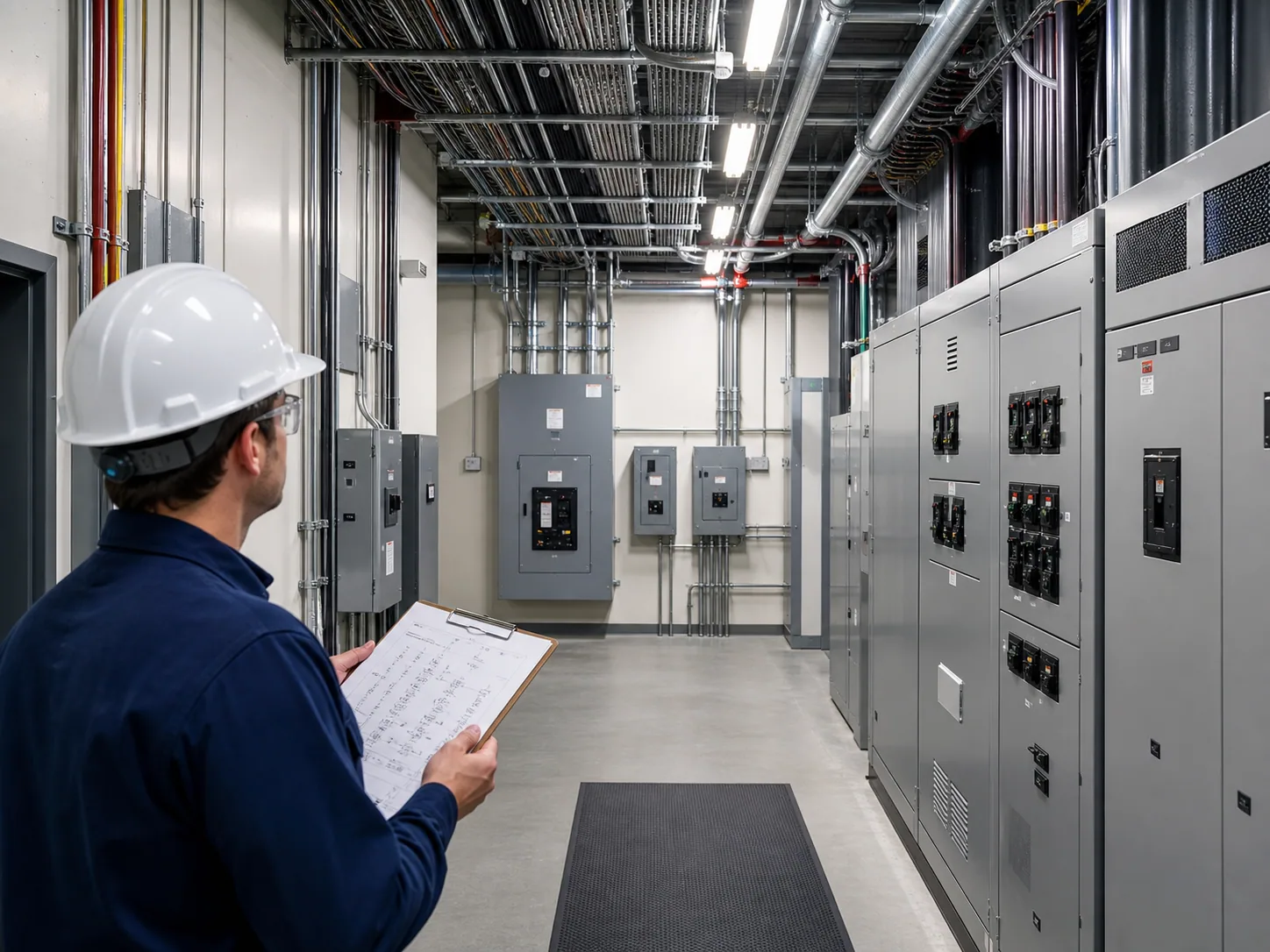
- For most commercial (non-dwelling) occupancies, the default is the Standard Method in Article 220.
- The load calc, panel schedules and one-line are three views of one system; they have to agree before the set goes out.
- Getting the load and service configuration in front of the utility early helps keep its requirements from becoming a redesign.
Sizing a commercial electrical service under NEC Article 220 means building up every load — lighting, receptacles, motors, HVAC, and special loads — applying the code’s demand factors, then confirming the load calculation, panel schedules, and one-line diagram all agree. When they don’t, the building department or the utility may flag it, and you can end up reconciling under a clock.
An electrical service load calculation determines the minimum service size needed to safely supply a building's loads while applying the NEC's demand-factor rules — the code's recognition that not everything runs at full load at once. But the number is only right if the load calc, the panel schedules, the one-line, and the utility's requirements all agree, which is where this actually gets interesting.
An electrical service size is a number that two separate reviewers can each check independently. The building department reviews code compliance, while the utility reviews the service information required by its standards. Consistent documents support review but do not guarantee building-department approval or utility acceptance. When your load calculation, panel schedules, and one-line don't tell the same story, you can get comments from one, a redesign request from the other, and a service you may have to re-coordinate after the drawings are "done."
Here's how we approach a commercial service calc so it holds up on both desks — grounded in NFPA 70 (the National Electrical Code), Article 220, which governs branch-circuit, feeder, and service load calculations.
Standard Method First
For most commercial (non-dwelling) occupancies, the default is the Standard Method in Article 220. You calculate the individual loads — general lighting, receptacles, motors, HVAC, kitchen equipment, and other fixed appliances — and apply the code's demand factors at the right stages. It's meticulous by design, because it has to account for every load.
There are optional methods, but they're narrow. NEC 220.88, for example, provides a single demand-factor procedure for new restaurants based on total connected load. There's also a method (220.87) for sizing to an existing service using measured maximum demand data — subject to a one-year demand record (or at least 30 days of continuous recording under its exception) and to that maximum demand, taken at 125 percent, plus the new load fitting the existing service. These are useful when the project qualifies — but you don't get to reach for them just because they're shorter. If the project doesn't fit the criteria, it's the standard method, full stop.
One note before anything else: confirm the NEC edition your jurisdiction has adopted. The 2023 NEC, which this article cites, is the most widely adopted edition; the 2026 NEC, now adopted in a growing number of states, moves these load-calculation rules to Article 120 (220.57 becomes 120.57, for example) and revises some of them. Article and table numbers, and some demand factors, move between editions.
Demand Factors: Connected Load vs. Calculated Load
The whole reason NEC Article 220 exists is that connected load (the sum of the installed equipment’s nameplate ratings) is not calculated load (what the service actually has to carry, built from the code’s prescribed unit loads and demand rules). Demand factors — the ratio of maximum demand to connected load, not to be confused with the diversity factor utility engineers use — bridge the two, built on a simple reality: in a real building, not every receptacle, lamp, and motor draws its maximum at the same instant.
The code applies demand factors selectively: some load types get a straight percentage reduction above a threshold (receptacle loads, certain feeders), some get a graduated schedule, and some — the ones that genuinely run at full load — get no reduction at all. Sizing the service on raw connected load "to be safe" isn't conservative engineering; it can mean an oversized service, a bigger main, and a larger utility transformer than the building needs — and it can still undercount loads the code requires you to count at a minimum value. The calculated load, done per the article, is the honest number — and the one a reviewer expects to see traced.
Continuous Loads and the 125% Rule
There's a rule that pulls the other direction from demand factors. A continuous load — one whose maximum current is expected to continue for three hours or more (most lighting, EV charging, dedicated ventilation) — must be sized at not less than 125% of its value for both the conductor and the overcurrent device (100% where the NEC permits an assembly listed for 100% operation; EV charger overcurrent protection stays at 125% under 625.41) — per 210.19(A) and 215.2(A)(1) for conductors, 210.20(A) and 215.3 for overcurrent devices, and 230.42/230.90 at the service. Articles 310 and 240 are where the resulting ampacity and protection requirements are then applied. A noncontinuous load carries no such adder. It's the code's thermal margin: gear carrying current for hours runs hotter than gear that cycles.
So a real service calc does both at once: it reduces diversified loads by demand factor and increases continuous loads by 125%. Getting the two straight is where a lot of calcs go wrong — applying the 125% to the wrong loads, or forgetting it on continuous lighting or an EV bank. The two rules aren't contradictory; they answer different questions (how much runs at once, vs. how long it runs), and the service has to satisfy both.
The Build-Up, Step by Step
A defensible service calc is really a disciplined build-up:
- General lighting load — by occupancy type, using the code's unit values (VA per square foot), then apply the lighting demand factors where allowed.
- Receptacle and general-use loads — computed and subject to their own demand factors for larger installations.
- Motor loads — the largest motor's full-load current taken at 125%, per the motor rules, plus the remaining motors at their full-load currents.
- HVAC / fixed equipment — the larger of heating or cooling where they won't run together, plus kitchen, elevator, and other fixed appliance loads with their applicable demand factors.
- Special loads — EV charging, data/IT, process equipment, and anything the project actually runs. This is where "code minimum" and "real building" diverge.
- Total and size the service — sum the demand loads, size the service and main, and confirm feeders and the neutral.
The output isn't just an amperage. It's a service size, a main device rating, feeder sizes, and a neutral that reflects the actual unbalanced and nonlinear load.
Service, Feeder, Transformer — and the Utility's Side
"Load calc" spans a few related sizings governed by different NEC articles, and it's worth keeping the distinction straight:
- Service (Article 230) — the service-entrance conductors and main, sized from the whole-building calculated load and typically landing in a switchboard or switchgear lineup.
- Feeders (Article 215) — each feeder to a downstream panelboard or MCC, sized from that panel's calculated load (same demand-factor logic, smaller scope).
- Load calculation itself (Article 220) — the method that feeds both.
- Transformer sizing — where the service is fed from an owner-owned transformer, it is sized to the calculated load with appropriate margin; a utility transformer is sized by the utility under its own criteria.
Then there's the boundary CoreX designs to but doesn't own: the utility's side. The design has to match the utility's requirements — available fault current (which sets equipment ratings and feeds directly into the short-circuit and coordination studies), metering form (self-contained vs. CT metering and a CT cabinet), the service voltage offered, and where the utility's transformer and service point land. CoreX prepares the service sizing under the engineer of record's direction and coordinates it to those requirements; the utility owns its transformer and its rules. Getting that coordination settled early helps avoid a service the utility won't energize.
Optional Methods, EV Loads, and Generator Interaction
Optional calculation methods. The standard method isn't the only path. NEC 220.87 lets you size from measured maximum demand on an existing building (useful for renovations and additions) — provided there is a one-year demand record (recording demand meter or utility data), or at least 30 days of continuous recording under its exception (15-minute demand on the highest-loaded phase, taken while the building is occupied and including the larger of the heating or cooling load and other seasonal loads; not permitted where the feeder or service has solar, wind or peak load shaving), and the maximum demand at 125 percent plus the new load stays within the existing feeder ampacity or service rating — and 220.88 is an optional method for qualifying restaurants.
| Method | Typical Use |
|---|---|
| Standard (Part III) | New commercial projects |
| 220.87 (existing loads) | Renovations / additions with metered history |
| 220.88 (optional, restaurants) | Qualifying restaurants |
EV charging. EV loads are continuous (125% applies) and increasingly large; the 2023 NEC counts each charger at the larger of 7,200 VA or its nameplate rating (220.57; earlier editions use the equipment rating) unless load management or a restricted-access adjustable setting limits it (625.42, with EMS limits under 220.70), so the design decision is whether to manage the chargers and how much future capacity to build in — under-provision and the next phase needs a service upgrade.
Generator interaction. Where emergency or standby power exists, the load calc feeds the generator sizing and the transfer scheme, the same classification and coordination work covered in our emergency and standby power guide. The service calc doesn't stop at the utility side; it hands off to the backup-power design.
The Calculation Chain — and Why It Has to Agree With Everything Else
Take an office floor (illustrative): total the general lighting (VA per square foot), the receptacle load, the HVAC and motor loads, and any special or kitchen loads. Apply the demand factors where the article allows, size the continuous portions at 125 percent of their value, and you get the calculated load — which sizes the service, the main breaker, and the feeders.
Here's the part that often gets skipped: that number can't live alone. The panel schedules have to reconcile with it through a traceable calculation (demand factors can be applied at different levels, so connected-load totals need not equal the service load), the one-line has to show a service and main that match, and the utility has to confirm it can serve it at the available fault current and metering form. Typical failure points include using connected load directly, forgetting the 125% on continuous loads, a panel schedule that doesn't reconcile with the service calc, or a one-line that shows a different main. A calc that's internally right but disagrees with the panel schedule is the kind of thing that can bounce at plan check.
The Reviewer's Real Test: Does Everything Agree?
Treat the load calc, the panel schedules, and the one-line as three views of the same system. They have to agree before the set goes out. Every large load on a schedule should be traceable in the calc; the service and main on the one-line should be sized from the calc's total. That's MEP coordination in miniature — one system, three documents, reconciled before anything is issued.
Headroom Without Hand-Waving
Owners add load. Tenants get built out. EV counts climb. Good electrical design leaves documented spare capacity — but documented is the operative word. Spare capacity that's shown as a deliberate provision (labeled spare breakers, reserved feeder capacity, a stated growth allowance) reads as engineering. A service padded 40% "to be safe" with no basis reads as guessing, costs the owner real money in gear and utility charges, and invites the reviewer to ask why. Locking the right amount of headroom is really a design-phase decision — cheap in schematic design, expensive once construction documents are underway.
Coordinate With the Utility Early
The city checks code; the utility checks their system. Service entrance location, metering, CT cabinets, transformer pad, available fault current at the service point — these are utility questions that can reshape your design if they surface late. Getting the load and the service configuration in front of the utility early helps keep their requirements from becoming a redesign after the drawings are set.
Further reading: Power-System Studies (Short-Circuit / Coordination / Arc-Flash) · Emergency vs. Standby Power (NEC 700/701/702 & NFPA 110) · MEP Coordination Best Practices
We run the standard method by default, reach for an optional method only when the project genuinely qualifies, and reconcile the load calc against the panel schedules and one-line before anything is issued. See our electrical services, or schedule a scope call.
Common Questions
The Standard Method in NEC Article 220 is the default approach for most commercial (non-dwelling) occupancies — you calculate each individual load (lighting, receptacles, motors, HVAC, kitchen equipment) and apply the code’s demand factors at the correct stages, then sum them to size the service.
NEC 220.88 provides an optional, simplified demand-factor procedure specifically for new restaurants based on total connected load — but only when the project actually qualifies under that section; otherwise the Standard Method applies.
The load calculation, panel schedules, and one-line diagram are three views of the same electrical system. Panel totals need not equal the service load, because demand factors can be applied at the feeder or service level, but the calculation has to trace from one to the other. The building department reviews code compliance, and the utility reviews the service information its standards require. If the documents disagree, a reviewer may not be able to tell which is the real design, so all three can be flagged for reconciliation.
The sum of every load’s nameplate rating in the building — before any demand factors. It is usually larger than the calculated load, but NEC minimum values can make the calculated value higher for some equipment — for example, 2023 NEC 220.57 counts EV charging equipment at 7,200 VA or its nameplate rating, whichever is larger.
The ratio of a load’s maximum demand to its connected load — applied in Article 220 as a code-permitted reduction reflecting the fact that not all loads draw their maximum simultaneously, turning connected load into calculated load.
An optional method that sizes the service from measured maximum demand on an existing building — useful for renovations and additions, but only with a one-year demand record (or at least 30 days of continuous recording while occupied, including seasonal heating or cooling loads, under its exception, which is not permitted where the service has solar, wind or peak load shaving), and only if the maximum demand at 125 percent plus the new load stays within the existing feeder ampacity or service rating.
A load whose maximum current is expected to continue for three hours or more — most lighting, EV charging, and dedicated ventilation. HVAC is not automatically in this category. A load in this category must be sized at not less than 125% of its value for the conductor and overcurrent device, unless the NEC permits an assembly listed for 100% operation; EV charger overcurrent protection stays at 125% under 625.41.
By totaling the loads (equipment nameplate ratings, or the prescribed unit loads in Article 220 where they apply), applying NEC 220 demand factors, sizing continuous loads at 125 percent of their value, and using the resulting calculated load to size the service, main, and feeders.
Under NEC Article 215, from the calculated load of the specific panel the feeder serves — the same demand logic as the service, at smaller scope.
Usually not, beyond the noncoincident-load rule — and HVAC is not automatically continuous either: take the larger of the noncoincident heating or cooling load per 220.60, and apply the Article 430/440 motor rules (including 125% of the largest motor-compressor). Treat a specific unit as continuous only where its maximum current will actually persist three hours or more. Fixed electric space heating is the exception: its branch-circuit conductors are sized at 125% of the load even when it cycles (424.4(B)).

Senior electrical designer with 6+ years in U.S. MEP design, contributor to 900+ projects, and an experienced third-party peer and plan reviewer.
Connect on LinkedIn →