DWV Sizing: Drainage Fixture Units, Slope, and the Venting Nobody Sees
A drainage, waste, and vent (DWV) system carries wastewater out of a building while keeping the piping near atmospheric pressure — so fixtures drain fully and trap seals keep sewer gas out of the occupied space. How it's sized — fixture units, slope, and venting — is where a plumbing design quietly succeeds or fails.
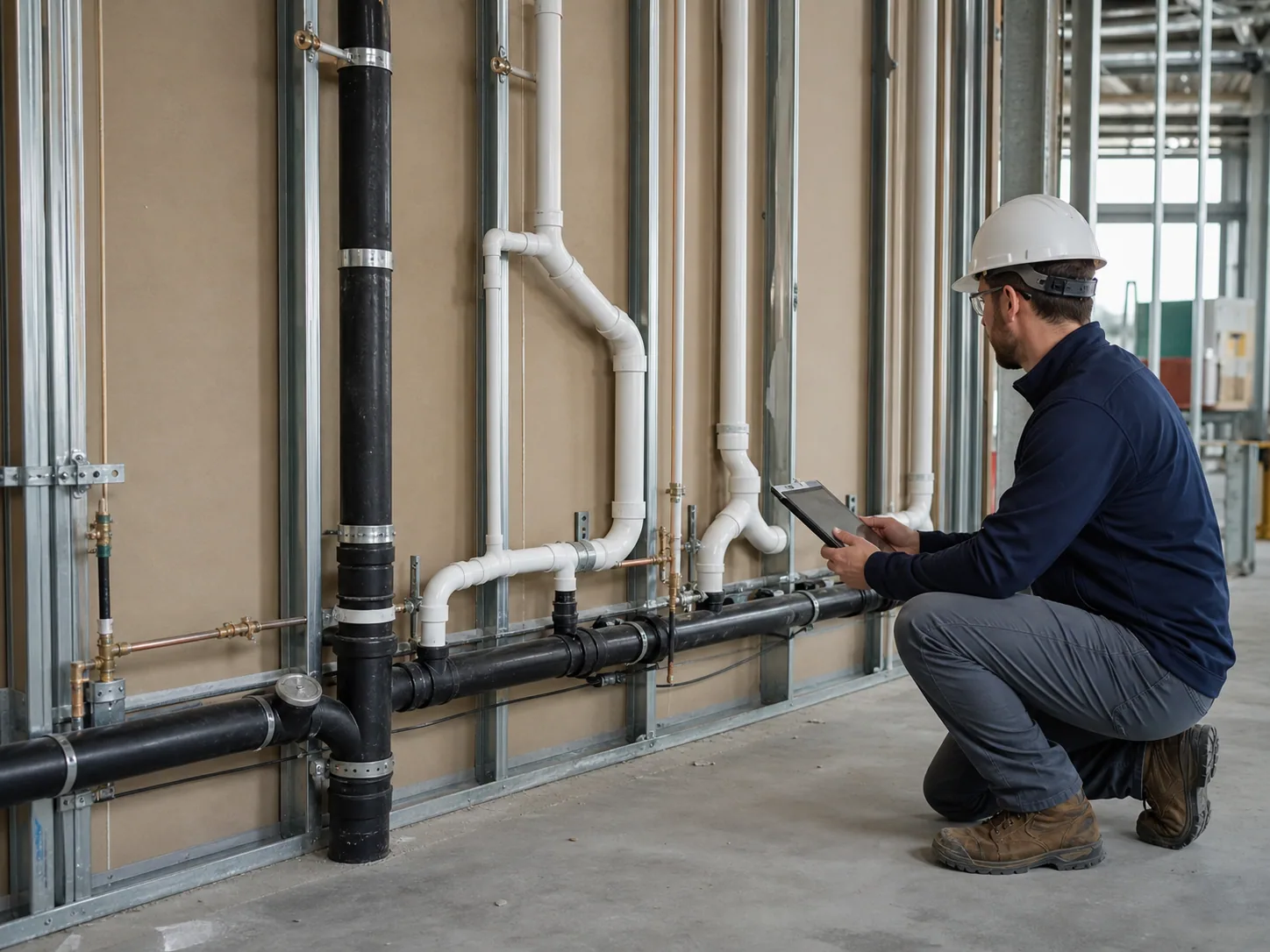
- Assign DFU values to every fixture, total them per branch, stack and building drain, then size from the code's drainage tables.
- Proper venting keeps the drainage system at near-atmospheric pressure so trap seals stay intact.
- The IPC and UPC use different tables and rules; design to the wrong one and the numbers won't match plan check.
DWV is half physics, half discipline. Here's how it actually gets sized.
DWV sizing assigns each fixture a drainage fixture unit (DFU) value, totals the DFUs per branch, stack, and building drain, and sizes pipe from the code's drainage tables. Horizontal drains are set to a minimum slope so solids carry, and the vent system is sized to keep the piping near atmospheric pressure so trap seals stay intact.
Drainage Fixture Units: The Drainage Cousin of WSFU
Just as water supply uses water supply fixture units (WSFU), drainage uses drainage fixture units (DFU) — a probability-based value representing the discharge load a fixture puts on the drainage system. A floor drain, a lavatory, and a water closet each carry different DFU values because they discharge different volumes at different frequencies.
You assign DFU values to every fixture, total them for each branch, stack, and building drain, and size the pipe from the code's drainage tables. The IPC and UPC each publish their tables, and they're built on the same underlying principle: size for realistic peak discharge, not for every fixture flushing at once. Confirm which code your jurisdiction has adopted — the tables and some rules differ.
Slope: Gravity Does the Work, If You Let It
Drainage is gravity-driven, so slope is everything. Too little slope and solids don't carry at today's low flush volumes — you get clogs. That's the code-enforced side, and the one that causes stoppages. Very steep runs are mainly a practical problem rather than a physics one: they eat invert fast and dump velocity into the base of the stack. Choose a compliant slope after checking capacity, available invert, connections, and installation tolerance. The code sets minimum slopes by pipe size: horizontal drains 2½ inches and smaller require ¼ inch per foot; 3 to 6 inches may run at ⅛ inch per foot, except that drains upstream of a grease interceptor need at least ¼ inch per foot (8 inches and larger, 1/16; IPC 704.1). The UPC (708.1) is stricter: ¼ inch per foot is its default, and in the current edition (2024 UPC, adopted in California as the 2025 CPC) ⅛ is allowed only on building drain piping 4 inches and larger, with prior AHJ approval, where ¼ is impractical. Those are code minimums, not targets. The design has to hold that slope across the whole run — which is a coordination problem as much as a plumbing one, because a long drain at 1/4 inch per foot drops fast and can collide with structure or ceilings below.
Venting: The Part That Protects the Trap Seal
Here's the piece that's invisible until it fails. Every fixture has a trap — that U-bend holding a small plug of water that blocks sewer gas from entering the building. Venting exists to protect that water seal. When water rushes down a drain, it can create positive pressure ahead of it and negative pressure behind it; without a vent to equalize, that pressure can either blow the trap seal out or siphon it dry. Either way, the barrier is gone and sewer gas comes through.
Proper venting keeps the drainage system at near-atmospheric pressure so trap seals stay intact. The code governs vent sizing, how far a vent can be from its trap (the "trap-to-vent" distance), and the configurations allowed — individual, common, wet, circuit, and stack venting among them. Under the IPC, stack vents and vent stacks are sized from developed length and the DFU load they carry, read off the code table (906.1), and are never less than half the drain they serve; individual, branch and circuit vents are at least half the drain size and never under 1¼ inch, upsized one pipe size past 40 feet of developed length (906.2); and the terminal is enlarged where frost closure is a risk. Get the venting right and drains run quiet, free-flowing and at a stable trap seal; get it wrong and you get slow, gurgling fixtures and, eventually, odor complaints that are miserable to diagnose after the walls are closed.
Branches, Stacks, and the Building Drain
Drains get sized in a hierarchy, and each level has its own rules:
- Horizontal branches collect a group of fixtures and carry them (at slope) to a stack. Sized from the branch DFU total.
- Stacks are the vertical pipes. A soil stack carries sewage containing fecal matter, typically from water closets; a waste stack carries liquid waste free of fecal matter; a vent stack carries no drainage at all — it runs vertically alongside the soil or waste stack solely to admit air and relieve pressure. Stacks are sized from the DFUs they carry and, under the IPC, limited by how many DFUs are allowed per branch interval — a tall multi-story stack can be limited by that interval rule as much as by total load.
- Stack offsets. When a stack has to jog horizontally (common in multifamily where units don't stack perfectly), the offset is a pressure and sizing event, not a free move — it can require re-venting and affects capacity.
- The building drain collects the stacks at the base and carries their DFU load out past the exterior wall to the building sewer. Its capacity depends on both DFU total and the slope it's run at.
- Building drain → building sewer. At a code-defined point just outside the building wall — the IPC and UPC set that distance differently — the drain becomes the building sewer; the transition point and the capacities on each side matter for the design.
Trap Arms, Vent Types, and Cleanouts
- Trap arm. The pipe from a fixture's trap to its vent. The code limits the trap-to-vent distance because too long a trap arm lets the drain self-siphon and pull the seal — so trap-arm length and slope are a real design constraint, not a field afterthought. For scale, under the IPC: 5 ft on a 1¼-inch trap arm, 6 ft at 1½, 8 ft at 2, 12 ft at 3 and 16 ft at 4 inches (the UPC differs — check the adopted code). Those distances keep the total fall at code slope within one pipe diameter, which is the logic behind the table.
- Vent types. Systems use several, chosen by layout: individual (one vent per trap), common (two fixtures share), wet (a drain doubles as a vent for another fixture — code-limited to specific fixture groups, sizes and loads, and materially more restrictive under the UPC), circuit (a shared vent for a row of battery fixtures), island fixture venting (a separate, code-defined method for island sinks, where no wall is available for a conventional vent), relief (relieves pressure on tall stacks), and stack vents. Where the code permits, an air admittance valve (AAV) can vent a fixture without a connection to the vent stack — but the restrictions matter: many UPC jurisdictions prohibit them outright, and even where permitted they must be accessible, set above the drain being vented and above any attic insulation, kept off chemical waste, and the building still needs at least one conventional vent terminating in open air.
- Cleanouts. Every drainage system needs accessible cleanouts at the code-required intervals — commonly no more than 100 feet apart on horizontal drains, with the IPC and UPC differing in the details — and at the changes of direction each code specifies, because drains will need rodding. A cleanout buried behind finish or above a hard ceiling is a maintenance failure designed in — accessibility is part of the design, not the contractor's problem to solve later.
Storm vs. Sanitary, and Pipe Materials
- Storm drainage is a separate system. Roof and site stormwater is sized and routed on its own — rainfall-rate and roof-area driven — and kept separate from sanitary DWV in most jurisdictions; older cities with combined sewers are the exception, so confirm with the AHJ. Wherever parapets or other roof-edge construction would trap water, the primary roof-drain system needs its secondary: scuppers or overflow drains sized for the blocked-primary condition. Building storm drainage — roof drains, secondary drainage, and storm piping inside the building — is still our work (site storm drainage is civil, by others), and it coordinates with the DWV design — at the podium/below-grade level especially, where storm, sanitary, and structure compete for the same space. Stack penetrations need any required sleeve or firestop system coordinated with the structural framing, and ceiling clearance has to be checked before the drawings go out. Don't conflate the two systems, but do coordinate them.
- Pipe materials. DWV is commonly PVC or ABS (light, easy to solvent-weld) or cast iron (heavier, but much quieter — often chosen in multifamily and hospitality precisely for acoustics, since a PVC waste stack behind a bedroom wall can become a noise complaint). Material choice affects installation, joints, support spacing, and sound — and it's a design decision, not just a contractor preference.
IPC vs. UPC: Why the Code Matters Before the Math
The two model plumbing codes size DWV on the same physics but with different tables and rules — and your jurisdiction has adopted one of them, the National Standard Plumbing Code (NSPC), or its own state plumbing code (Illinois and Wisconsin, for example). Design to the wrong one and the numbers won't match plan check.
| IPC (International Plumbing Code) | UPC (Uniform Plumbing Code) | |
|---|---|---|
| Publisher | ICC | IAPMO |
| DFU tables | Its own values & sizing tables | Different values & tables |
| Venting rules | Permits certain configs (e.g., some AAV/island venting) | Often more restrictive on some methods |
| Where adopted | Varies by state/jurisdiction | Varies by state/jurisdiction |
Values and permitted methods differ by adopted edition — always confirm the jurisdiction's adopted code and edition before sizing. Don't copy a previous project from a different jurisdiction.
From Fixtures to Pipe: The Sizing Sequence
Take a small office restroom group: total the DFUs for the water closets, lavatories, and a floor drain; that branch total sizes the horizontal branch from the drainage table. Roll the branches into the stack, check the per-interval DFU limit, and size the stack. Sum every stack into the building drain and size that at its design slope. Then size the vents — individual or common at the fixtures, trap arms kept within the trap-to-vent limit, and a stack vent terminating through the roof as the roof vent.
Where it collides with the building: a long building drain at 1/4-inch-per-foot drops fast, so it competes with structure and the other trades' ceiling space — DWV routing is as much an MEP coordination problem as a sizing one. The invert has to clear beams and land where the sewer connection is. Getting slope, invert, and routing coordinated on the drawings is what keeps it from becoming a field conflict after the slab is poured.
Where DWV Design Goes Wrong
The common failures are predictable: undersized stacks that can't carry peak discharge, horizontal runs that lose their slope over distance, venting that's too far from the trap or simply undersized, and — on multi-story work — stacks and offsets that aren't coordinated with structure. Much of it traces to treating DWV as an afterthought instead of a system — sized once early in design development and never revisited as the rest of the building solidifies around it.
How CoreX Handles It
We size DWV as deliberately as supply — DFU totals per the adopted code, pipe sized from the drainage tables, slope held across the full run and coordinated against structure so it fits, and venting designed to keep every trap seal intact. On multi-story and multifamily work especially, where stacks repeat and offsets stack up, that discipline helps separate a drainage system designed to limit noise, protect trap seals, and support maintenance from one that generates callbacks. That same discipline shows up hardest in restaurants & food service, where grease waste and floor drains multiply fixture-unit loads fast; in healthcare & medical work, where redundancy and code scrutiny leave no room for a missed vent; and in commercial & office buildings stacking the same core plumbing chase floor after floor.
Related: Sizing Domestic Water (WSFU / Hunter's Curve) · MEP Coordination Best Practices · How to Read MEP Drawings
If your plumbing production needs DWV done right, we prepare it under your engineer of record’s direction and seal. See our plumbing services and Residential & Multi-Family, or schedule a scope call.
Common Questions
A drainage fixture unit (DFU) is a probability-based value representing the discharge load a fixture puts on the drainage system — the drainage counterpart to a water supply fixture unit (WSFU). A floor drain, a lavatory, and a water closet each carry different DFU values because they discharge different volumes at different frequencies. DFU values are assigned to every fixture, totaled for each branch, stack, and building drain, and used to size the pipe from the code's drainage tables.
The code sets minimum slopes by pipe size. Horizontal drains 2½ inches and smaller require ¼ inch per foot; 3 to 6 inches may run at ⅛ inch per foot, except upstream of a grease interceptor, where ¼ inch is the minimum (8 inches and larger, 1/16; IPC 704.1; the current UPC keeps ¼ inch as its default and allows ⅛ only on building drain piping 4 inches and larger, with AHJ approval, where ¼ is impractical) — code minimums, not targets. That slope has to be held across the entire run — too little and solids don't carry at today's low flush volumes; that's the code-enforced side, and the one that causes stoppages. Very steep runs are mainly a practical problem rather than a physics one: they eat invert fast and dump velocity into the base of the stack. Choose a compliant slope after checking capacity, available invert, connections, and installation tolerance.
Every fixture has a trap holding a small plug of water — the trap seal — that blocks sewer gas from entering the building. When water rushes down a drain it can create positive pressure ahead of it and negative pressure behind it; without a vent to equalize that pressure, it can either blow the trap seal out or siphon it dry. Venting keeps the drainage system at near-atmospheric pressure so trap seals stay intact and sewer gas can't get through.
The drainage, waste, and vent system: it carries wastewater out while keeping the piping near atmospheric pressure so fixtures drain and trap seals stay intact.
From the DFUs the stack carries and, under the IPC, the limit on DFUs per branch interval; a tall stack can be governed by the interval rule as much as by total load.
A soil stack carries sewage containing fecal matter, typically from water closets; a waste stack carries liquid waste free of fecal matter.
The pipe from a fixture's trap to its vent. The code limits its length (trap-to-vent distance) because too long a trap arm lets the drain siphon the seal dry.
Drains need rodding over their life; the code requires accessible cleanouts at set intervals and changes of direction. An inaccessible cleanout is a maintenance failure designed in.
Yes, within code rules (a dry vent generally rises at least 6 inches above the flood-level rim of the highest fixture served before running horizontally, and is pitched to drain back), but the configuration and connection points are governed — it's not a free horizontal run.
Same physics, different tables and permitted venting methods; jurisdictions adopt one or the other (a few use the NSPC or their own state code), so the sizing has to match the adopted code and edition.
One cause is a lost trap seal — pulled by siphonage or blown by pressure when venting is inadequate, or a dried-out trap on an unused fixture. Proper venting and trap-seal protection, such as trap primers on rarely used drains, reduce that risk; leaking drains or vents and failed fixture seals can also cause sewer-gas odor.

Senior electrical designer with 6+ years in U.S. MEP design, contributor to 900+ projects, and an experienced third-party peer and plan reviewer.
Connect on LinkedIn →